|
V3 Assembly Steps: 0 1 2 3 4 5 6 7 8 9 10 11 12 13 14 15 16 17 18 19 20 21 22 23 24 25 26 27
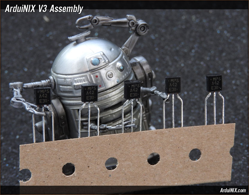
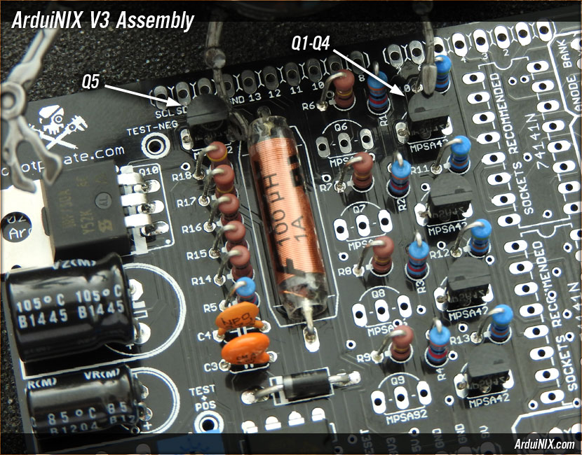
Step 18: Q1 - Q5 = 5x MPSA42 Hi voltage transistors Watch the orientation on these transistors, making sure they match the diagram. Make sure you read the labels correctly on all transistors and don't mix them up! Q1 through Q4 should be installed in a row to the left of the driver chip area. Q5 is at the top of the board to the left of the coil. Once installed, they should look like the photo below, flat side toward the bottom.
V3 Assembly Steps: 0 1 2 3 4 5 6 7 8 9 10 11 12 13 14 15 16 17 18 19 20 21 22 23 24 25 26 27 |
|
|
|
The ArduiNIX is a RobotPirate Project; a nonentity production : Questions? Email Bradley |
||