|
V3 Assembly Steps: 0 1 2 3 4 5 6 7 8 9 10 11 12 13 14 15 16 17 18 19 20 21 22 23 24 25 26 27
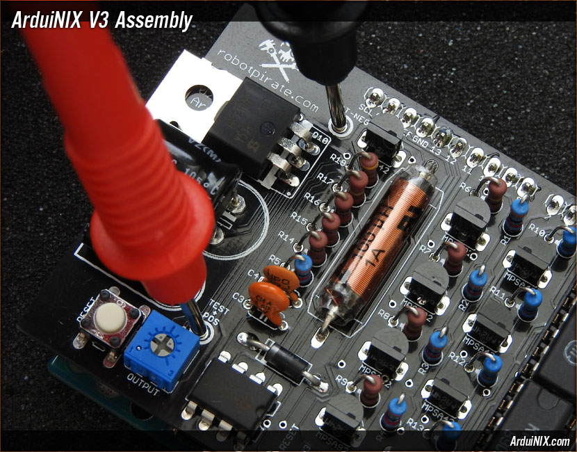
Step 26: Test Output Voltage Plug a 9V 650 milliamp or greater DC adapter into your Arduino. WARNING: Be very careful with the unit once it's charged. Once plugged in, certain portions of the ArduiNIX will become charged with high voltage. Do not touch the anode pins, or test points, or any exposed solder points while the unit is charged. Locate the test points labeled TEST+POS and TEST-NEG. Set your multimeter to DC Voltage, and place the positive lead into the pad at TEST+POS. Place the negative lead into the pad at TEST-NEG. Be careful not to touch any other components at this time.
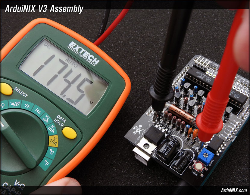
The ArduiNIX, when properly configured, should have an output range sufficient to drive most neon based nixie tubes that require approximately 100 to 200 volts. For general settings, try setting the output to between 175 and 180 volts.
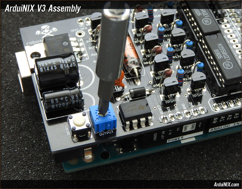
Adjust the trim pot counterclockwise to raise the output voltage. Clockwise to lower it. Once you have set the output to your desired voltage, unplug the 9V DC Adapter from the Arduino to power down. You'll download the code to your Arduino next. V3 Assembly Steps: 0 1 2 3 4 5 6 7 8 9 10 11 12 13 14 15 16 17 18 19 20 21 22 23 24 25 26 27 |
|
|
|
The ArduiNIX is a RobotPirate Project; a nonentity production : Questions? Email Bradley |
||