|
V3 Assembly Steps: 0 1 2 3 4 5 6 7 8 9 10 11 12 13 14 15 16 17 18 19 20 21 22 23 24 25 26 27
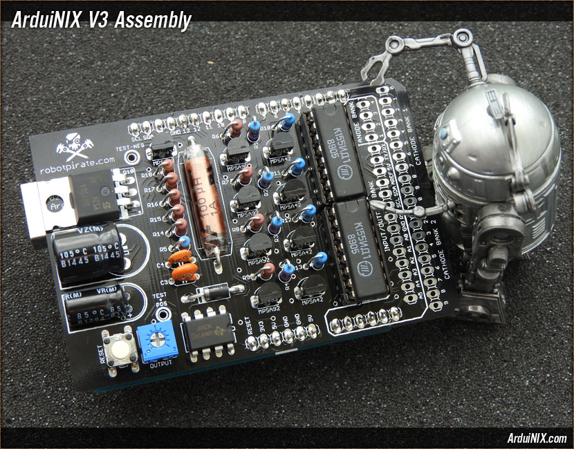
Step 25: Check your work! Check your work - solder welds, alignment and orientation of components. Check for bridged traces or pads. Make sure your timer, driver chips, and polarized capacitors are in the proper orientation. Now double-check. It's important to have everything in the proper place and orientation for the first bootup so you don't fry any components. We claim NO RESPONSIBILITY if your board fails due to bad assembly. Assemble the ArduiNIX Shield to the Arduino board. With that step complete, your ArduiNIX Shield is ready for voltage testing. The ArduiNIX kit does not include connector rails for the cathodes and anodes. The way you connect your ArduiNIX Shield to your tubes is up to you. We prefer ribbon cable and angled or straight pin rails, but you may prefer hardwiring. The ArduiNIX connects to your nixie tubes through the terminals labeled CATHODE BANK 1 and 2, and ANODE BANK. The cathodes connect to the numeral plates 0 through 9 on the nixie tube, and the anode terminals connect to the anode pin of your nixie tube. ALWAYS use a resistor between the anode terminal and the anode pin of your nixie tube. This is required. The value of the resistor varies depending on your tubes, but 10K works well to start with. The anode rail is the high voltage output for the ArduiNIX Shield. It supplies driving voltage to the anode pins of your tubes. Make sure to use a resistor between the anode terminals and the anode pin on the tubes of your choice. Each anode terminal is designed to handle up to two anode connections, meaning the four anode terminals will support up to eight nixie tubes total. V3 Assembly Steps: 0 1 2 3 4 5 6 7 8 9 10 11 12 13 14 15 16 17 18 19 20 21 22 23 24 25 26 27 |
|
|
|
The ArduiNIX is a RobotPirate Project; a nonentity production : Questions? Email Bradley |
||