|
V3 Assembly Steps: 0 1 2 3 4 5 6 7 8 9 10 11 12 13 14 15 16 17 18 19 20 21 22 23 24 25 26 27
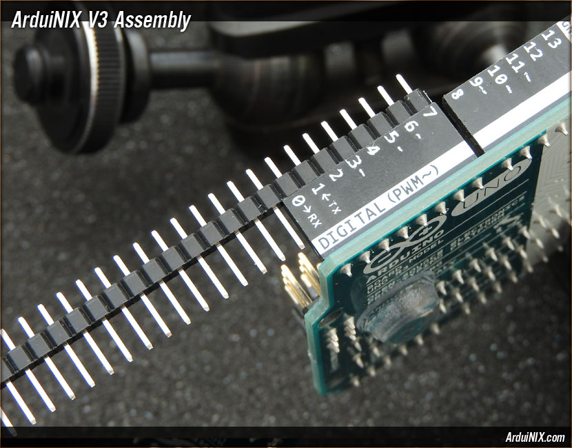
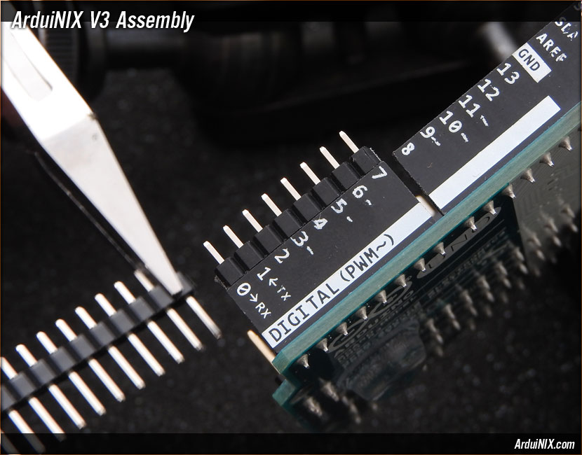
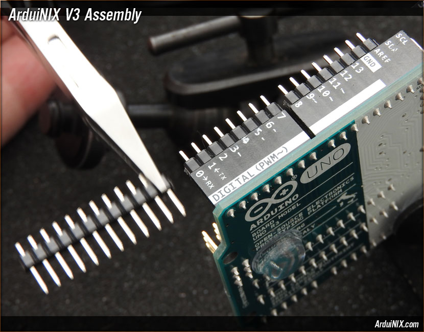
Step 22: Pin Rail Assembly: Data Side = 40 Pin 2.54mm Single Row Breakaway Header Pin Rail Place eight pins on the end of the pin rail into the DIGITAL (PWM~) section of the Arduino.
Break the excess pin rail after 0->RX.
For older Arduinos, move the eight-pin section of rail from DIGITAL (PWM~) to the next section as in the photo. For newer model Arduinos with SCL and SDA ports, place a ten-pin section of rail in the header marked "SCL" through "8." The ArduiNIX V3 will break out these connections at the input/output section of the board. No need to solder in access at this location. You may want to use any leftover pin rail sections for either the anode header or the input/output breakout section. V3 Assembly Steps: 0 1 2 3 4 5 6 7 8 9 10 11 12 13 14 15 16 17 18 19 20 21 22 23 24 25 26 27 |
|
|
|
The ArduiNIX is a RobotPirate Project; a nonentity production : Questions? Email Bradley |
||